There has been a lively discussion on the MSA-Talk e-mail list the past few days on the subject of optical mineralogy. Life in a Plane Light has a very nice summary of the discussion and an update of other posts that came in after the first summary.
I have been following the conversation with interest because optical mineralogy is very important to metamorphic petrologists. For those of you who are not familiar with the process a brief description is in order. Step one is to obtain an interesting rock from the field—break off a hand-sample from the outcrop (a chunk of rock small enough to carry in your hand), record on your map the location from whence it was obtained, and write down any important observations you have made about the outcrop (how large is it, does it contain more than one rock type? What sort of contacts separate the rock types? What structures are present? If your sample has any structures which are measurable (foliation, lineation, strike & dip of the rock itself) measure them *before* obtaining your sample, and make marks on the rock with a waterproof marker showing what you measured and what the measurements were—then carefully break that portion of rock away from the outcrop without destroying the marks.
Why is step one so important? Because knowing the field relationships of your sample really helps your understanding of what you will see in the thin section once you have it.
Step two is the creation of the thin section. To do this we use a rock saw to cut the hand sample open. If there are structures of interest in the sample (foliations, lineations, etc.) it is important to make the cut at an angle of interest. There are times when one wishes to see the minerals parallel the structure, times when one wishes to the minerals perpendicular to the structure. If the structure is complex one will likely wish to make more than one thin section of the rock at more than one angle.
We use the saw to cut a small rectangular block of rock out of the hand sample, with one of the long sides of the rectangle oriented in the direction of interest. If your sample is an "oriented" sample (it has marks on it showing what was measured in the field) take care to transfer those marks onto the small block so that you will know which way is "up" or "east" or "north", or whatever orientation you have marked. Once the hand sample is a small block we polish one side of it (the one which is oriented in the direction of interest with respect to the structure) and when it is very smooth we "glue" that side to a glass microscope slide (using a rock appropriate epoxy). At this point we record the sample name on the glass, and also transfer any marks showing the orientation of the sample to the glass itself (this can be done low-tech by scratching on the glass with a nail, or high-tech by using a laser, or with a few other options in between of intermediate technology levels) After the epoxy has set we use a rock saw to cut away most of the rest of the block of rock (which we save for later comparison with the thin section—it can be helpful to also polish the face of this block that was closest to the glass before removing it).
The next step is to polish the thin layer of rock which is attached to the glass slide. This is done carefully because at the end of the process we wish the layer of rock remaining attached to the slide to be only 30 microns thick (remember that there are 1000 microns in every millimetre). The reason we wish it to be that thin is because at this thickness many of the rock forming minerals are translucent—light will pass through them.
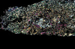
This is where the "optical mineralogy" part really begins. By using a petrographic microscope we can see and identify the minerals in the sample and see their relationship to one another. How do we do this? By carefully comparing the various features we can see with an understanding of the features usually displayed by minerals. A course in optical mineralogy teaches us how to distinguish one mineral from another based on their colour or lack thereof, how high is their "relief" (does it appear to stand up above the plane of the glass slide, appear to be lower than that plane, or more or less lie in the plane?), what is its crystal habit of each of the minerals? All of these clues, taken together, permit us to recognize the minerals.
Once we know which minerals are present we can then make observations of how they relate to one another. Are they all aligned with their long axis parallel to the same direction (foliated)? Is that alignment a planar feature, or is it folded? Is there more than one foliation? Are some minerals present only totally surrounded by (included within) certain other minerals? When minerals are present both as inclusions and within the matrix is there any difference between them? (are the inclusions smaller or larger than the same mineral in the matrix? Are they oriented the same direction in both locations? Is there a colour change from one to the other?
These are just a few of the things we look for in a thin section to help unravel the story of the rock. When I was an undergraduate student we not only had a dedicated course in optical mineralogy, but it was a requirement of the course to make one thin section ourselves, starting from collecting the sample in the field and ending with a report about all of the minerals present in the sample and their relationship to one another and what we learned about the rock thereby. In those days we had to make a drawing of the thin section which showed these relationships.
Now days we have fancy, high-tech optical microscopes with motorized sample stages that are attached to powerful cameras and computers. As a result we can program the machines to take a series of photographs at very close scale of thin section, then "stitch" them together to make a single high-resolution image of a large portion of the thin section, which we can then annotate in a drawing program, labelling the minerals, tracing the structures, etc. For those of us who are not practiced artists this is a much better approach for illustrating what we see in the thin sections. However, in the old days a talented petrologist with a steady drawing hand was able to do drawings of thin sections which are works of art and which show an amazing amount of detail of what is in the sample. For a good example of this check out the book Metamorphic Textures by Alan Spry, published in 1969 (ISBN: 0080133169 / 0-08-013316-9), which appears to be available for purchase in pdf form these days, though I haven't tried to do so.