Having recently started a position as a post-doc with an experimental petrology team it is now time for me to make the transition from reading a huge stack of background material to actually doing experiments. This requires learning a whole new skill set, like welding. Here follows the notes I’ve made on the first few steps of creating sealed capsules full of material to be taken to elevated temperatures and pressures during my forthcoming experiments. This is mostly for my own information, but someone out there might find it interesting or useful (or have helpful comments they can add), so I’ll share it here. *Step one: Prepare the holder in which the capsule will be placed while filling it
 During the filling process we use small metal disks into which holes of varying diameter have been drilled as a holder for the capsules (different sized holes are needed because different experiments use different sized capsules). First find a disk which has a hole with the correct diameter (or make a new hole in a disk if necessary). It needs to be just big enough to insert the tube into, without being loose. Then use fine sandpaper to carefully polish the metal around that hole so that when you get to step 6 you will have an easier time of filling the capsule.
*Step two: cut the tube for the capsule
 For my experiments I will be using capsules made of gold tubing that is 2 mm outside diameter (1.4 mm inside diameter).
Obtain the correct diameter and metal tube (our lab uses both gold and platinum/gold alloys in a variety of sizes, I’m to use gold for mine) and then cut off a ~7 mm length from one end. To cut the tubing place it on a metal plate, then place an x-acto blade upon the tube and use the blade to exert a gentle pressure to roll the tube back and forth until the blade cuts through without squishing the tube. The back-and-forth motion is essential. This is not “sawing”, which uses a serrated blade to tear chunks out of a material which is stationary, but rather the tube itself rolls during the process as the blade slowly cuts into it.
*Step tree: Pinch closed one end of the tube
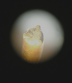
 To seal the first end of the tube use pliers which have slightly rounded side edges. It is important to use the correct tool, as the sharp sided pliers can pierce a hole in the gold between the unpinched and pinched portions of the tube. (However, one of my colleagues uses the straight-sided ones, but he is very, very careful.) We use a three-part closure, which looks much like a symmetrical peace symbol. In order to create this do it in stages, don't try to squeeze it to final tightness on the first go, that won't work. Instead do a little at a time, slightly pinching on one side, turn the tube 1/3 of a rotation and pinch again, repeating around the tube, tightening the pinches a bit more each pass. Ideally, one wants it to be closed all the way to the center without leaving a hole at the triple junction. Unfortunately, this is difficult to achieve when working on such a small tube with pliers which are so much larger than the tube. Once the end is pinched shut trim the three edges using a cutting tool with beveled edges. The reason for wanting beveled edges to the cutter is so that the place where the two edges of gold meets is as narrow as possible, which will make welding easier. Hold the cutter at a slight angle so that once trimmed the triple point at the junction is slightly higher than the far ends of each of the three seams. (This photo, above left, taken through the microscope, shows a crimped tube held in place in the clamp and ready to weld.)
*Step four: Weld the pinched end shut

The voltage necessary for welding will change based on a variety of factors, including the diameter and length of the capsule, the thinness of the seam, the sharpness and length of the graphite in the welding tool, and what, if anything, you use to cool the capsule as you work. Unfortunately, our
welder isn't very precise and it can be difficult to adjust it to the perfect voltage for any given job. For this size we tried a variety of settings between 25 and 30 V, the 25 V was clearly too low--the welder left it looking "dirty" and coated with black, which is graphite from the welder being left on the gold. At 30 V it was too high; there is too much melting. In between that range the exact value was hard to find, and as variables change, so does the perfect voltage for the task. One variable which can make a huge difference is the sharpness of the graphite point. We have two different sharpeners, one of which makes a sharper point than the other. Using a “point” created by the duller of the two sharpeners at a voltage which isn’t high enough for that point and then switching to a point created by the sharper of the two sharpeners without turning down the voltage will result in the entire end of the tube melting.
The bit of advice I obtained the next day seems to have made a difference—don’t try to touch the gold with the graphite point, but rather hold it just barely close enough to cause an arc between them, and then try to draw that arc along the length of the seam. This isn’t easy, but I did wind up with useable results. Alas, the photo to the upper left doesn't show the welding very clearly--gold is just too darn shiny to photograph well through a microscope with a cheap camera when resting in a brass holder (this is after adjusting the brightness/contrast/intensity to make it visible at all).
I was also told that when welding I should try to start at the outer edge and draw the graphite point towards the middle, which brings excess gold from the edge towards the center to fill the small hole at the triple-junction. The goal is also to wind up with a flat bottom after welding.
*Step five: Prepare the welded tube for filling
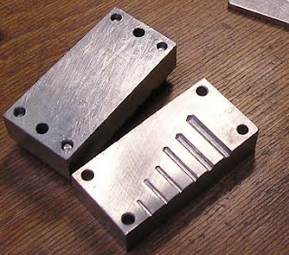 After welding the tube it is necessary to re-shape the tube so that the capsule will have properly rounded/curving edges. We have a form (photo to the left) into which the tube is placed carefully so that the widest parts will be inside the form and not pinched between the two halves of the form (one chooses the correct diameter chamber within the form for the tube in question, of course). Once it is positions correctly the form is closed, and the tube is pressed back into a cylindrical shape. Once it has been re-shaped in the form it is put it into the holder (prepared in step one, and resting on a metal plate) and insert into the gold tube a small rod which has a diameter which just fits into the tube (in this case the rod needs to fit into a space 1.4 mm wide). Gently tap the rod with a mallet so that the bottom of the capsule flattens against the underlying metal plate and spreads out to match the curve of the sides of the hole in which the tube rests (take care as to not strike it so hard as to tear a hole in the gold tube!).
After much effort I now have three small capsules with one end of each sealed and flattened, and the other end still open and ready to fill. Stay tuned for steps 6 and 7 once I get them working. Having finally managed to get the tubes ready to fill, I chose to rest on my laurels and call it good for the day.




 Posts
Posts

